
Installing Outdoor Cam Pro PoE
Safety and compliance information for Outdoor Cam Pro.
Get step-by-step installation instructions for your Outdoor Cam Pro PoE.
Download the user manual for Outdoor Cam Pro PoEDownload/view the manual for Outdoor Cam Pro PoE (French)Download/view the manual for Outdoor Cam Pro PoE (Spanish)Hardware included

Tools needed

Phillips-head screwdriver

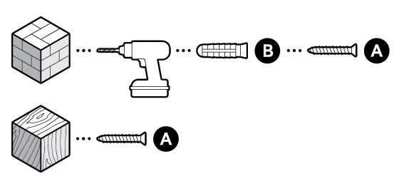
Drill with 5 mm masonry bit (optional)

Caulk gun
- Remove the protective wrap.
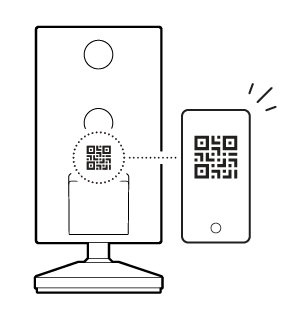
- Download the Ring app.

- Scan the QR code on your device.
- Choose a location.


NOTE: Before installation, ensure your Power over Ethernet (PoE) switch capable of PoE+ is active and connected to a functioning Category 5 Ethernet cable.
Junction box installation
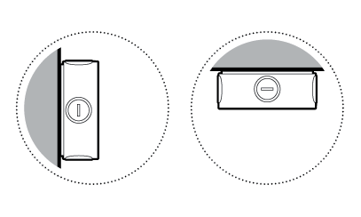
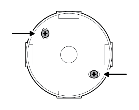
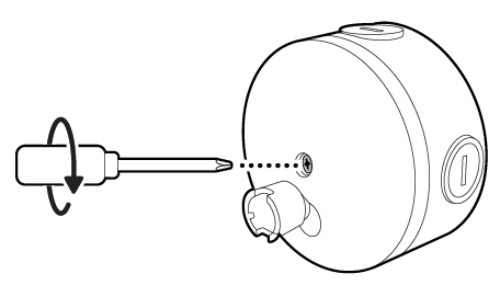
- Use a coin to unscrew a cap from the side or back of the junction box.
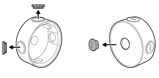
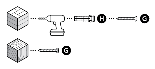
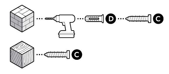
- Install the included junction box on the wall or ceiling with the included screws. On stucco, brick, or concrete, use a 3/16 in (5 mm) masonry bit to drill holes for the wall anchors included with your adapter.
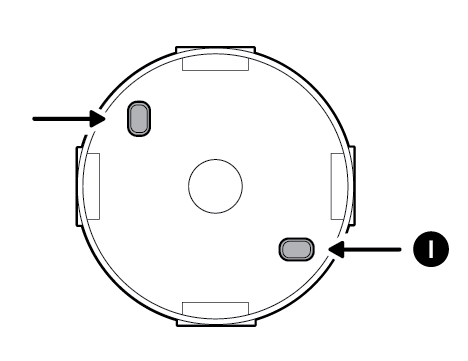
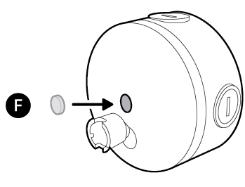
- Cover the screw holes with the included plugs.
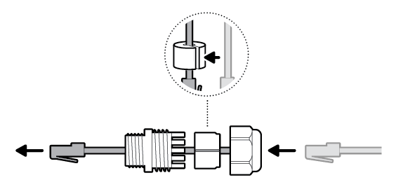
- Disassemble the cable gland by unscrewing the cap from the body.
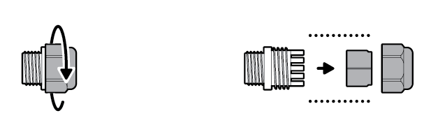
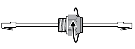
- Thread the Ethernet cable through the cable gland, wrapping the O-ring around the cable, and screw tightly until there is a secure seal.
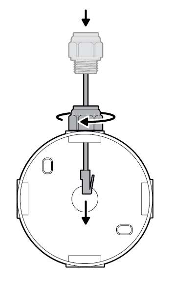
 NOTE:If installing the junction box directly over your PoE switch, you do not need to attach the cable gland.
 - Insert the Ethernet cable through the knockout, ensuring the cable gland is snug.
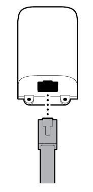
- Plug the Ethernet cable into the adapter.
- Plug the USB-C cable within the junction box cover mount into the adapter, ensuring it is fully inserted.
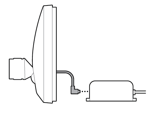
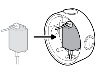
- Slot the adapter into the center of the junction box.
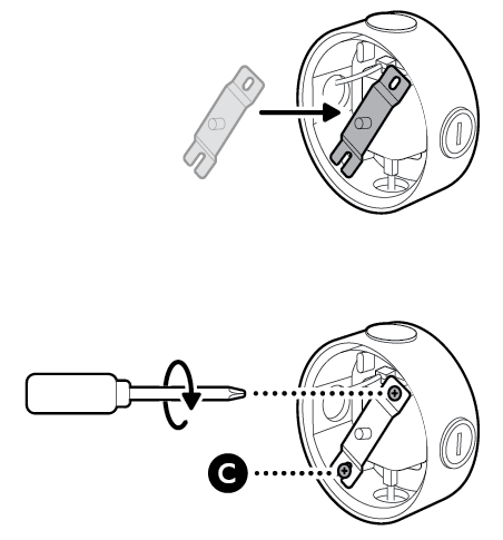
- Attach the metal crossbar with the screws included with your adapter, starting with the closed screw hole.
- Close the junction box with the cover mount.
- Tighten the center screw to secure the junction box cover mount in place.
- Cover the center screw hole with the included plug.
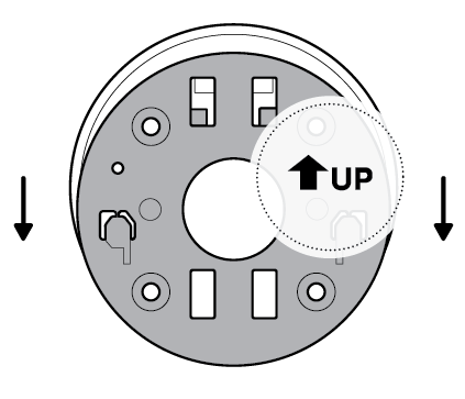
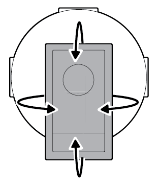
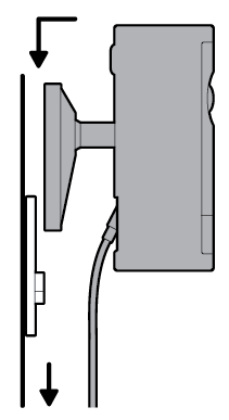
- Slide the mounting plate in the direction opposite to the UP arrow to remove.
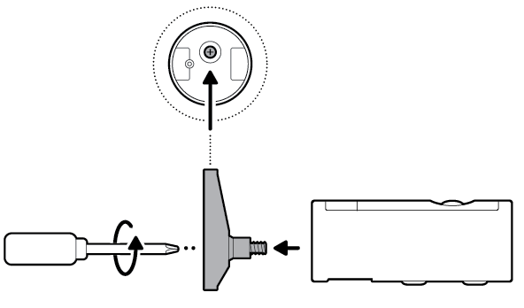
- Unscrew to detach the camera mount.
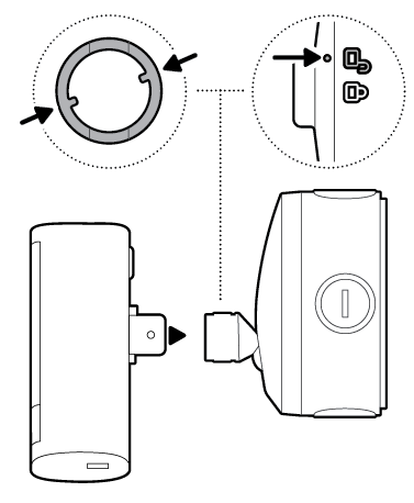
- Remove the middle rubber cap on the back of your camera.
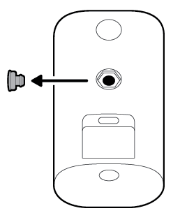
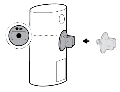
- Tighten the included hex joint onto the back of your camera, ensuring the UP indicator is pointing up.
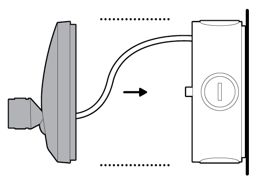
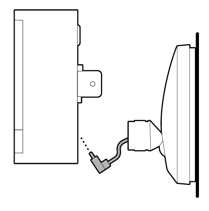
- Plug the USB-C cable on the junction box cover mount into your camera, ensuring it is fully inserted.
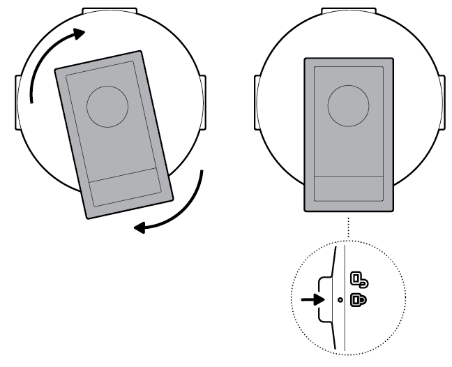
- Align the hex joint with the junction box cover mount and insert.
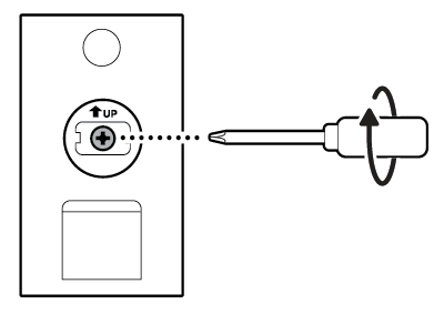
- Turn until your camera locks in place.
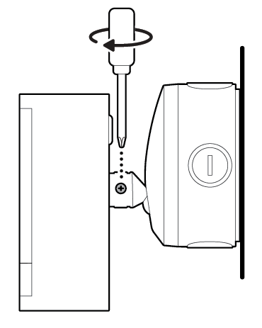
- Tighten the security screw.
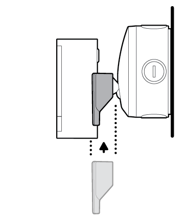
- Install your camera's decorative cover by sliding until you hear a click to secure.
- Adjust your camera's position, if necessary.
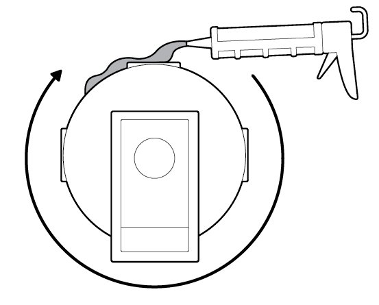
- Apply proper silicone or caulk around the junction box knockouts, between the junction box and junction box cover mount, and between the junction box and mounting surface to seal any gaps.


Flat installation
FOR INDOOR USE ONLY
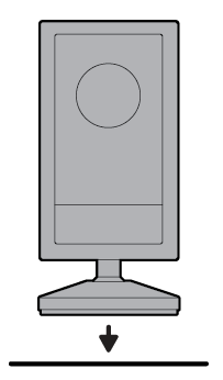
- Place your camera on a level surface.
- Plug the Ethernet cable into the adapter.
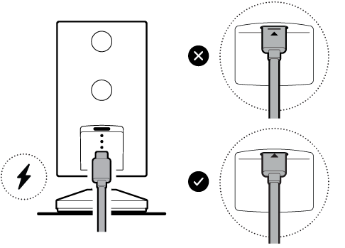
- Plug the included USB-C cable into the adapter until the indicator line disappears.
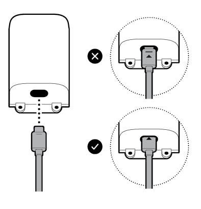
- Plug the other end of the USB-C cable into your camera until the indicator line disappears.


Wall installation
FOR INDOOR USE ONLY
- Slide the mounting plate in the direction opposite to the UP arrow to remove.
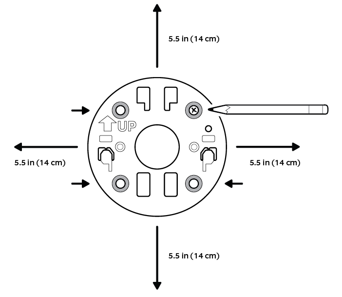
- Use the mounting plate as a guide to mark screw holes on the wall with 5.5 in (14 cm) of space in every direction.
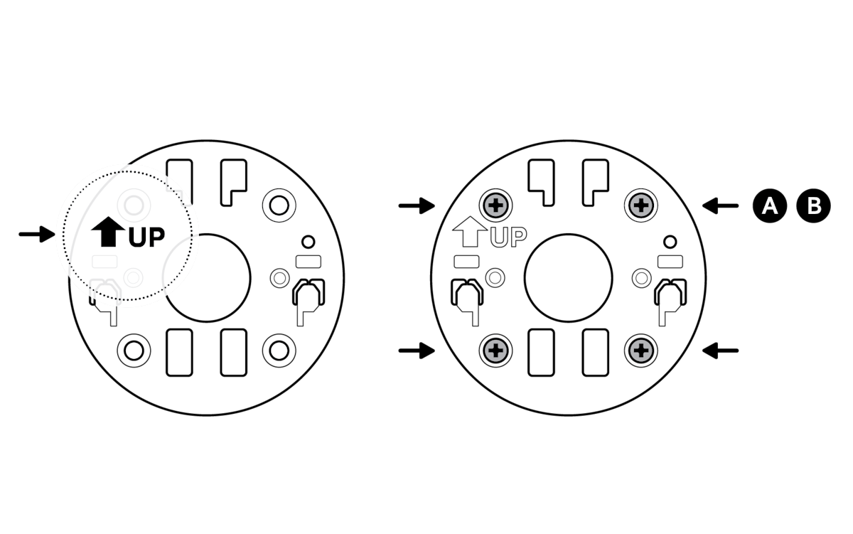
- Install the mounting plate with the UP arrow pointing up. On stucco, brick, or concrete, use a 3/16 in (5 mm) masonry bit to drill holes for the included wall anchors.
- Unscrew to detach the camera mount.
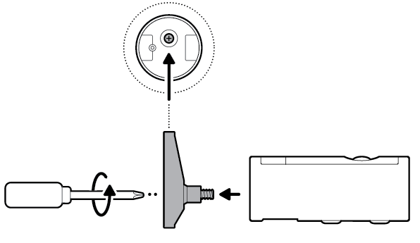
- Remove the middle rubber cap on the back of your camera.
- Attach the camera mount to the back of your camera with its screw.
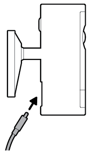
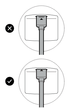
- Plug the included USB-C cable into your camera until the indicator line disappears.
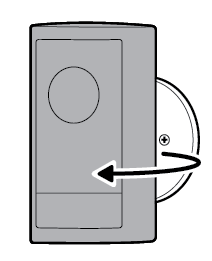
- Secure your camera to the mounting plate by sliding until you feel a click.
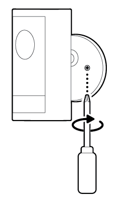
- Rotate your camera and tighten the security screw.
- Install the adapter on the wall with the included screws. On stucco, brick, or concrete, use a 3/16 in (5 mm) masonry bit to drill holes for the included wall anchors.

- Plug the other end of the USB-C cable into the adapter until the indicator line disappears.
- Plug the Ethernet cable into the adapter.


Ceiling installation
FOR INDOOR USE ONLY
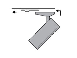
- Slide the mounting plate in the direction opposite to the UP arrow to remove.
- Use the mounting plate as a guide to mark screw holes on the ceiling with 5.5 in (14 cm) of space in every direction.NOTE:For best results, avoid locations with nearby objects that can interfere with your camera's field of view.
- Install the mounting plate with the UP arrow pointing toward your desired viewing direction. On stucco, brick, or concrete, use a 3/16 in (5 mm) masonry bit to drill holes for the included wall anchors.
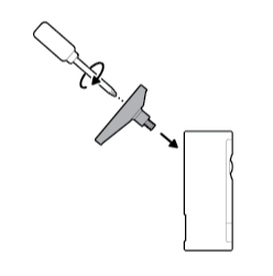
- Unscrew to detach the camera mount.
- Remove the top rubber cap on the back of your camera.

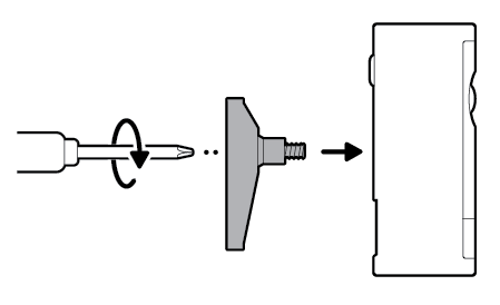
- Attach the camera mount to the back of your camera with its screw.
- Secure your camera to the mounting plate by sliding until you feel a click.
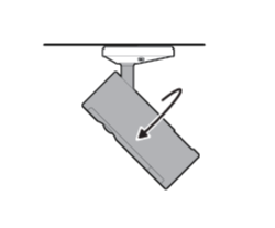
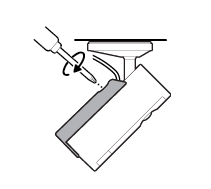
 NOTE:Your camera should be in an upright position.
 - Rotate your camera and tighten the security screw.
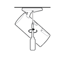
- Plug the included USB-C cable into your camera until the indicator line disappears.
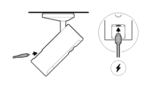
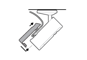
- Slide the included cable bracket onto the back of your camera and tighten the handscrew to secure your power cable.
- Install the adapter on the wall or ceiling with the included screws. On stucco, brick, or concrete, use a 3/16 in (5 mm) masonry bit to drill holes for the wall anchors included with your adapter.
- Plug the other end of the USB-C cable into the adapter until the indicator line disappears.
- Plug the Ethernet cable into the adapter.


Last updated 9 months ago