
Hardwired Kit for Cameras Installation Guide
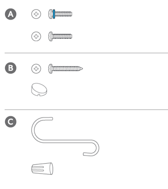
Download/view the install guide for Hardwired Kit for CamerasHardware included:
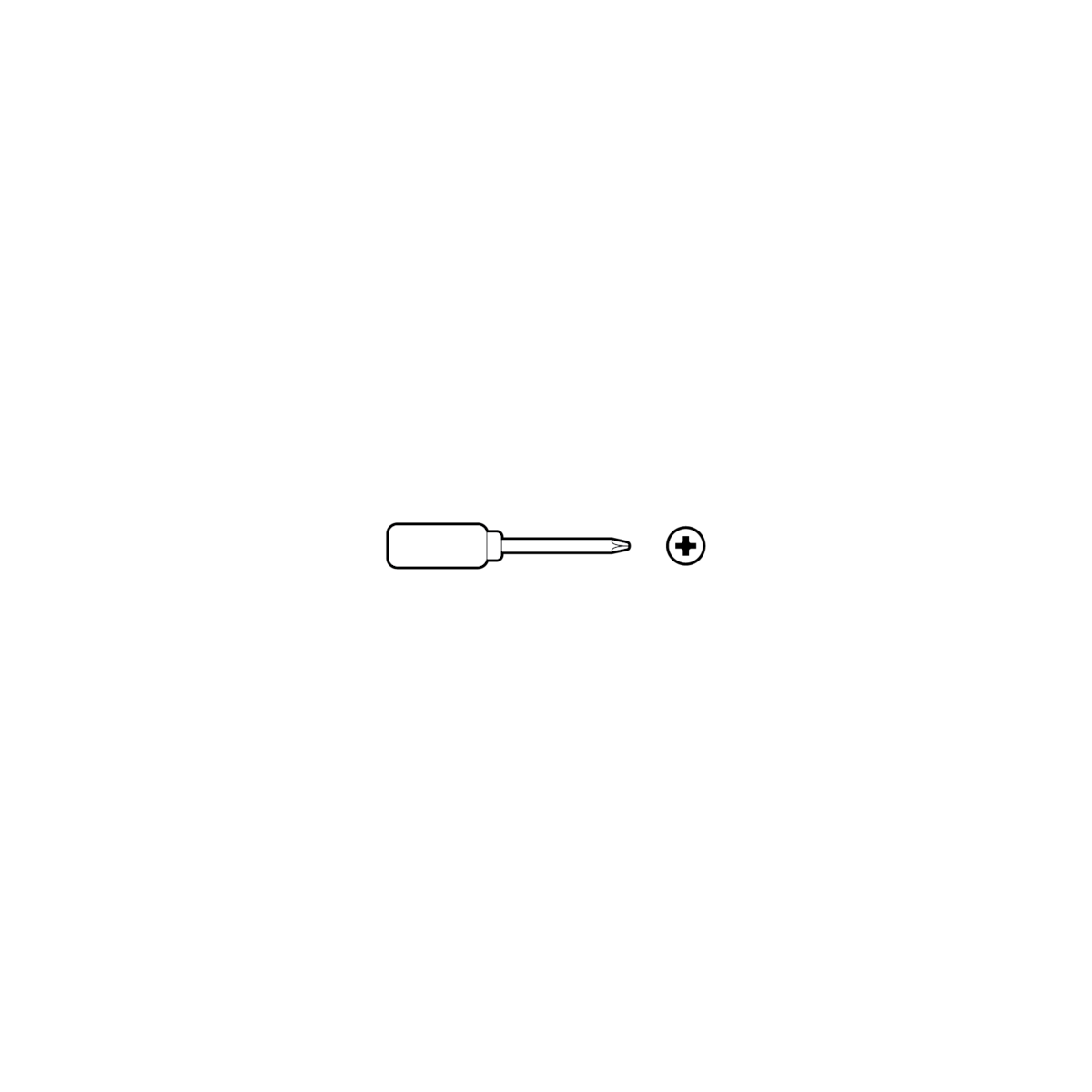
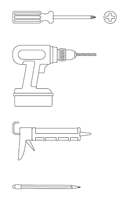
Tools needed:
Shut off power at the breaker.
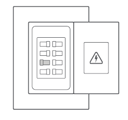
Note: If your power system is classified as OVC Ill, please check the building "Distribution Panel", Ex switch panel has an installed Surge Protectors. Ensure that the surge protector is a UL 1449 certified Surge Protector to reduce Main Transient Voltage to Overvoltage Category II (2500 V pk or lower) before connecting to all AC Inputs. If the there is no Surge Protector, do not install the Hardwired Kit without one.
Before you begin installing your Hardwired Kit, make sure that you're following safety code standards.
WARNING: Electrical shock hazard. Disconnect power to installation area at your circuit breaker or fuse box before beginning installation. Always use caution when handling electrical wiring. Installation by a qualified electrician may be required in your area. Refer to your local laws and building codes before performing electrical work; permits plus professional installation may be required by law. Your Hardwired Kit must be installed on a 4" round UL listed weatherproof electrical box when installed outdoors.
For installing out-of-wall, 4-inch metal and plastic junction boxes.
WARNING: Inspect your junction box before installing your Hardwired Kit. If you notice any signs of water ingress, pooling water, visible condensation, or rusted or corroded metal components, consult a qualified electrician in your area before proceeding with installation.
Requires a minimum 14AWG or higher 3-core cable.
Optional: Temporarily install a machine screw to hold the S-hook for help connecting the wires. Remove the temporary screw after wires are connected.
1. For metal: Connect the green earth wires with junction box earth screw. (Home protective earthing and wired mount bonding conductor wires) See connection diagram. Then connect the white (N) and black (L) wires with wire nuts.
WARNING: If you can't easily identify the wires coming out of your junction box, or have difficulty with or are uncomfortable connecting them, consult a licensed electrician.
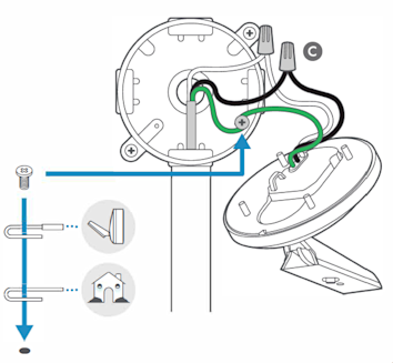
For plastic: Connect the green earth wires with a wire nut. (Home protective earthing and wired mount bonding conductor wires) See connection diagram. Then, connect the white (N) and black (L) wires with wire nuts.
WARNING: If you can't easily identify the wires coming out of your junction box, or have difficulty with or are uncomfortable connecting them, consult a licensed electrician.
Optional: Temporarily install a machine screw to hold the S-hook for help connecting the wires. Remove the temporary screw after wires are connected.
Note: If you ever need to remove for metal and plastic:
Remove the white (N) and black (L) wires. Then, remove the wired mount bonding conductor wire and the home protective earthing conductor wire.
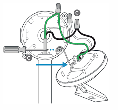
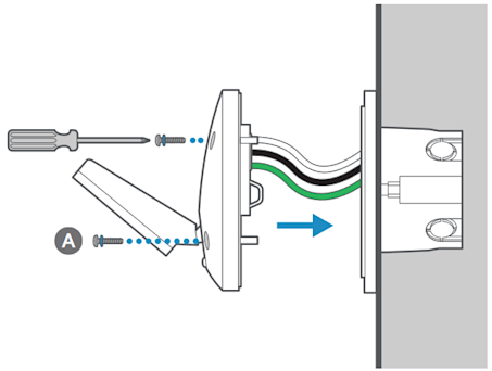
2. For metal and plastic: Gently put the wires in the junction box and secure the wired mount to the adapter plate with 2 machine screws with o-rings.
3. For metal: Then, tighten the screws into the wired mount until the foam backing fully seals the junction box to prevent water from entering.
For plastic: Take 4 o-rings off the machine screws and apply them to 4 tapping screws. Then, tighten the screws into the wired mount until the foam backing fully seals the junction box to prevent water from entering.
For in-wall and out-of-wall junction boxes:
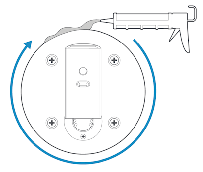
4. Apply a weatherproof silicone caulk or sealant around the outside where the wired mount and junction box or wall meet to prevent water from entering the junction box.
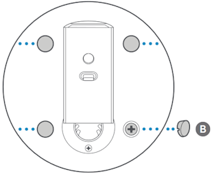
5. Apply cosmetic screw plugs.
For installing in-wall, 3.5-inch plastic junction box and switch box.
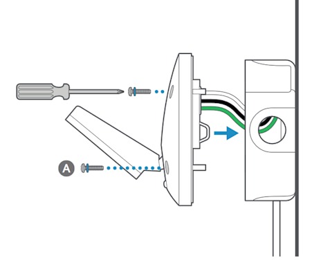
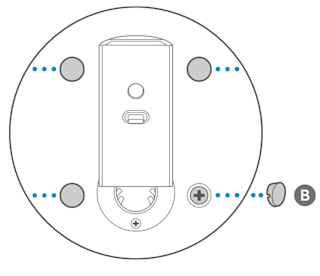
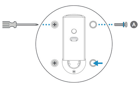
1. For junction and switch box: Attach the adapter plate to junction box with 2 tapping screws.
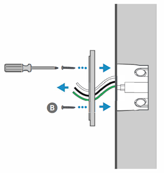
Requires a minimum 14AWG or higher 3-core cable.
2. For junction and switch box: Connect the green earth wires with a wire nut. Then, connect the white (N) and black (L) wires with wire nuts.
WARNING: If you can't easily identify the wires coming out of your junction box, or have difficulty with or are uncomfortable connecting them, consult a licensed electrician.
Optional: Temporarily install a machine screw to hold the S-hook for help connecting the wires. Remove the temporary screw after wires are connected.
Note: If ever needed to remove for metal and plastic:
Remove the white (N) and black (L) wires. Then, remove the wired mount bonding conductor wire and the home protective earthing conductor wire.
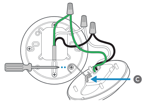
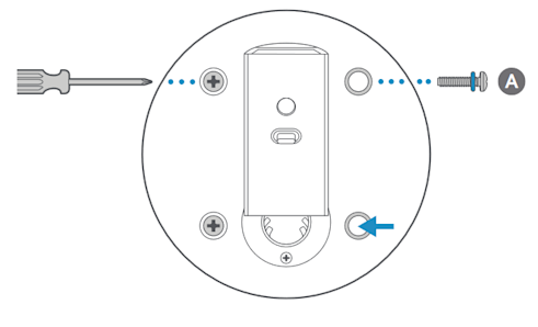
3. For junction and switch box: Stuff the wires gently into the junction box and screw the wired mount to the adapter plate with 4 machine screws with O-rings.
4. For junction and switch box: Then, tighten the screws into the wired mount until the foam backing fully seals the junction box to prevent water from entering. (1.37-1.47N/m of torque force)
Then, tighten the screws into the wired mount until the foam backing fully seals the junction box to prevent water from entering. (1. 37-1.47N/m of torque force)
For in-wall and out-of-wall junction boxes:
5. Apply a weatherproof silicone caulk or sealant around the outside where the wired mount and junction box or wall meet to prevent water from entering the junction box.
6. Apply cosmetic screw plugs.
For Spotlight Cam Pro or Plus
Choose a location.
Refer to wall or ceiling installation depending on the location you choose.
1. Remove weather cover.
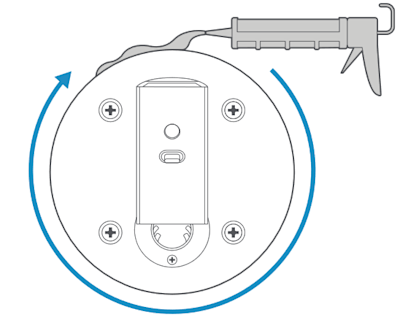
2. Remove the battery cover and camera backplate.
Twist the cover counter-clockwise and slide out the backplate.
3a. For Wall Installation

3b. For ceiling installation
4. Connect USB-C cable.
Plug the USB-C cable in to your camera's USB-C port.
5. Attach weather cover.
Snap into place to cover exposed cables.
6. Adjust camera angle.
Tighten the ball joint screw to secure the camera in place.
For Outdoor Cam Plus or Stick Up Cam Pro
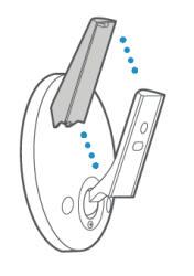
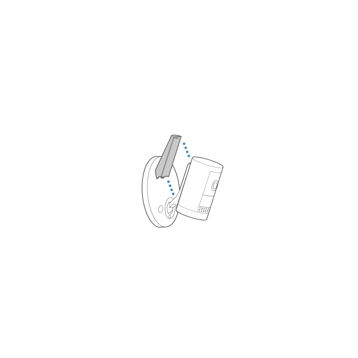
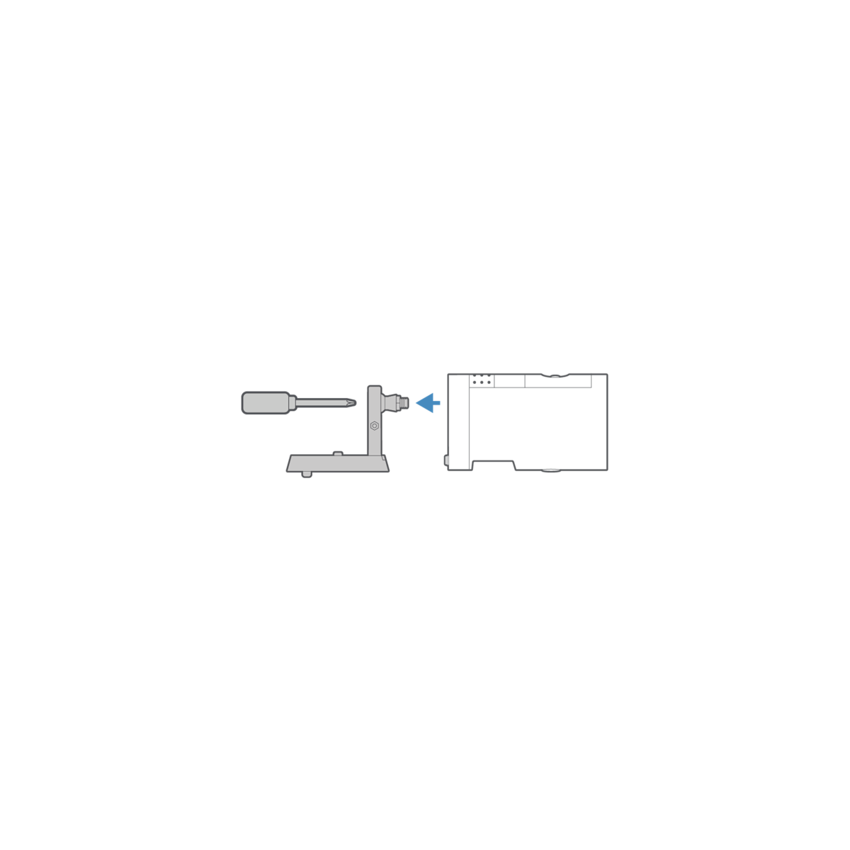
1. Unclasp the camera mount.
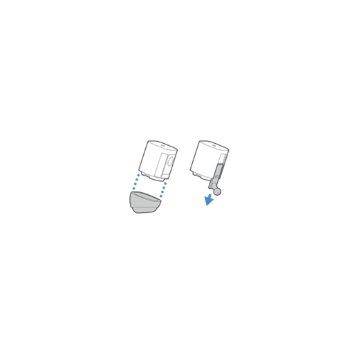
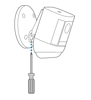
2. Unscrew to detach the camera mount from the battery cover.
Choose a location.
Refer to wall or ceiling installation depending on the location you choose.
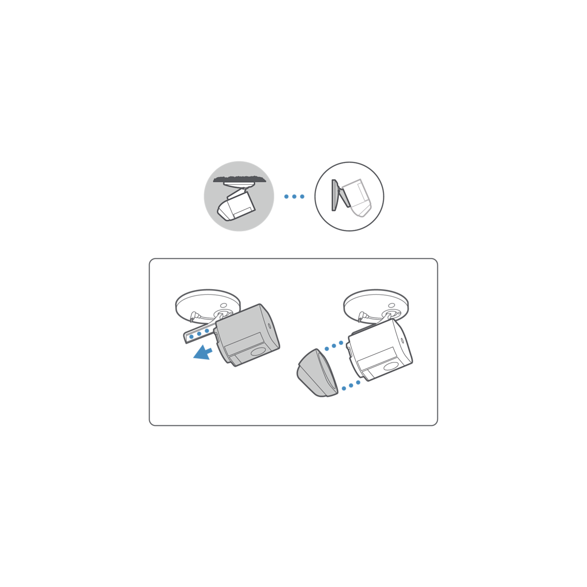
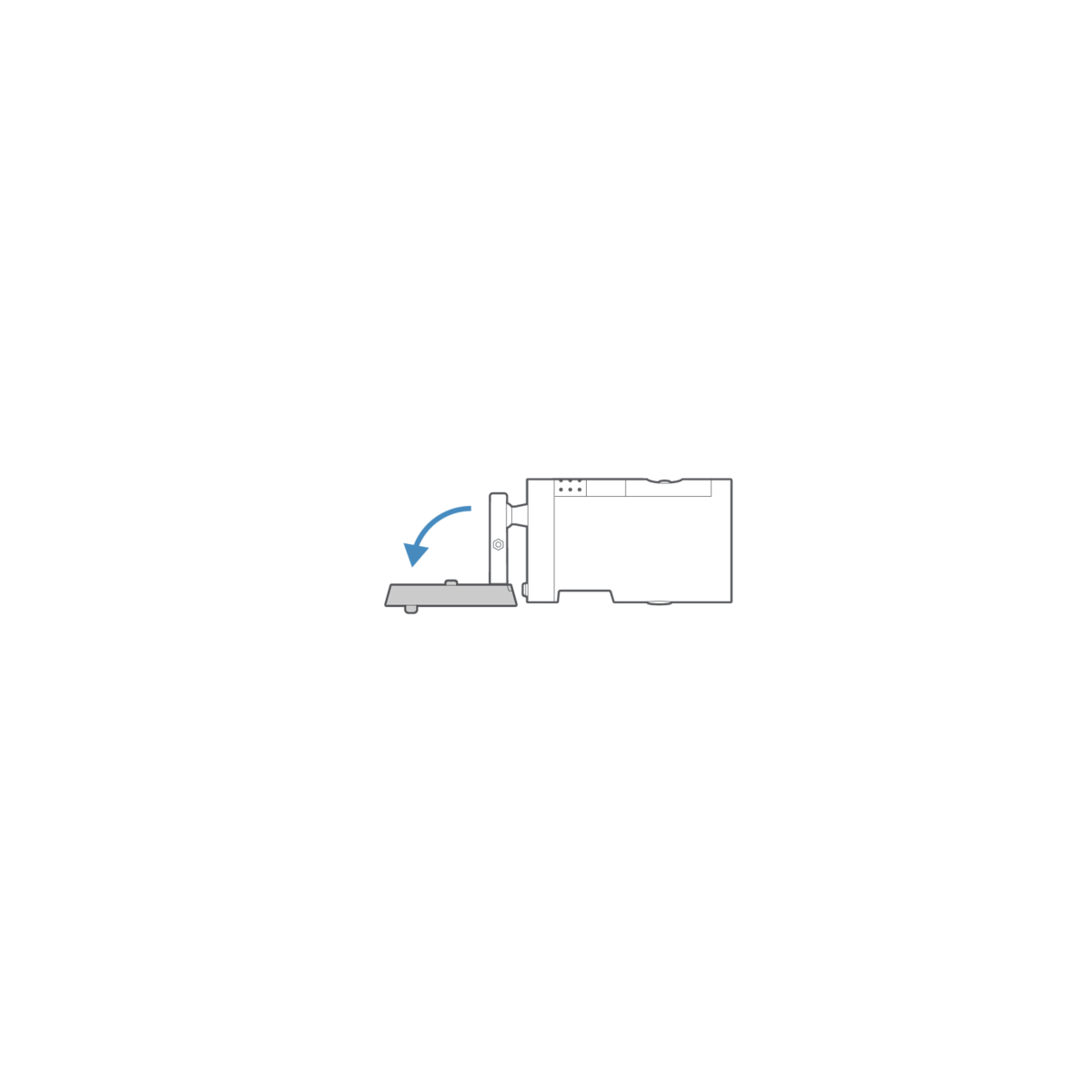
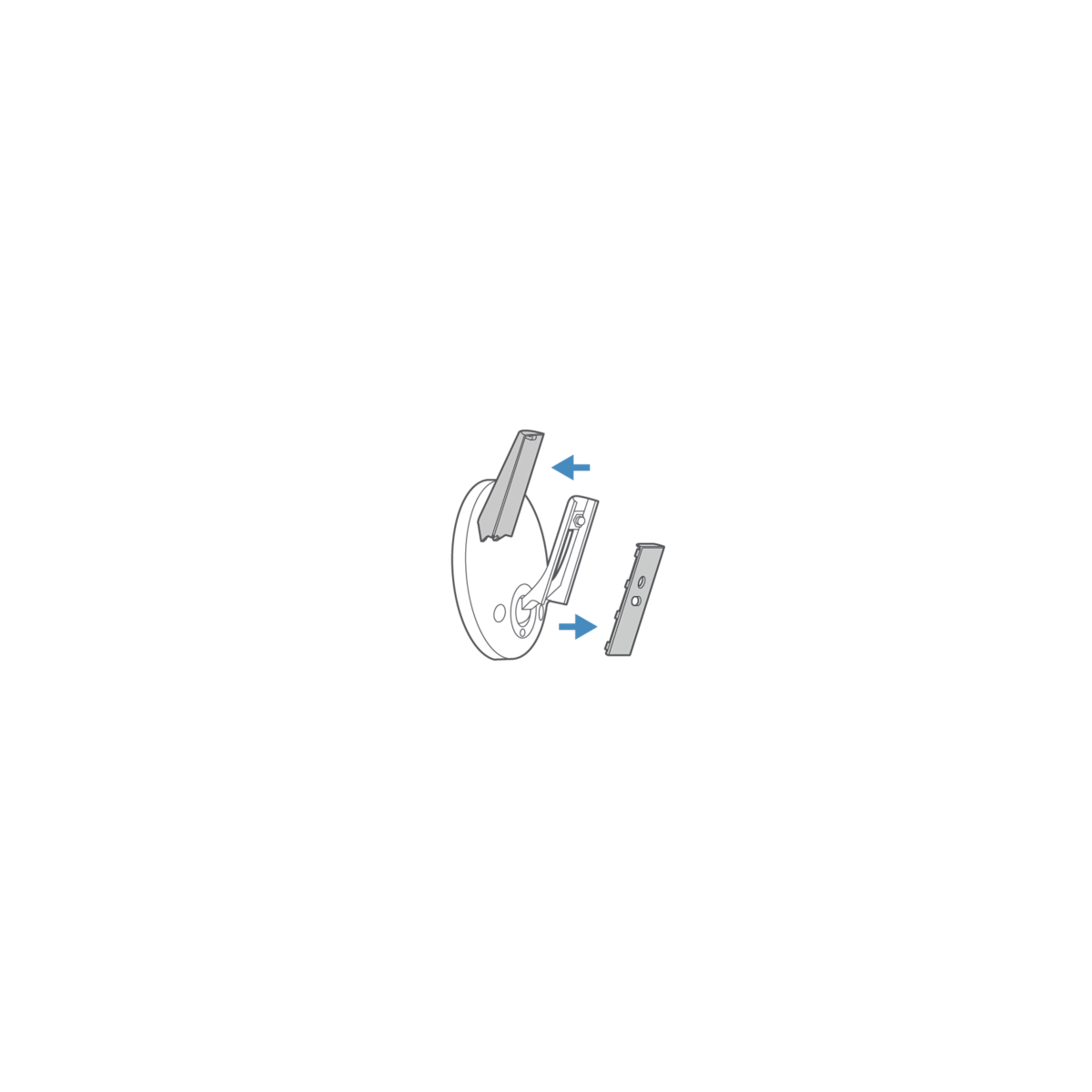
3. Remove the weather cover and wired mount arm plate adapter.
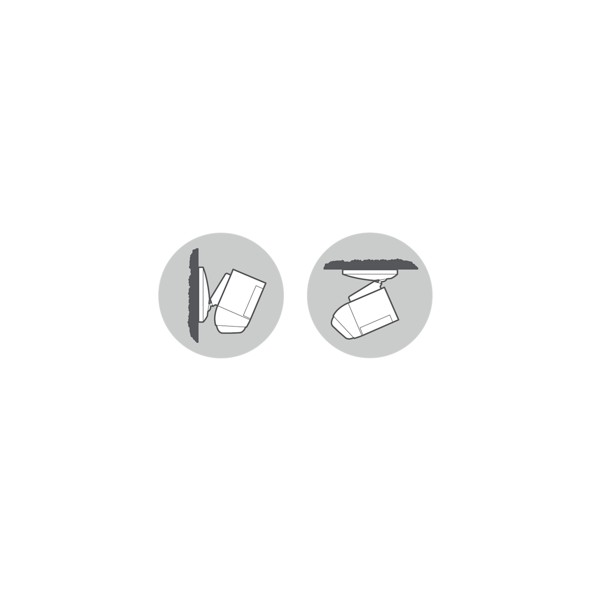
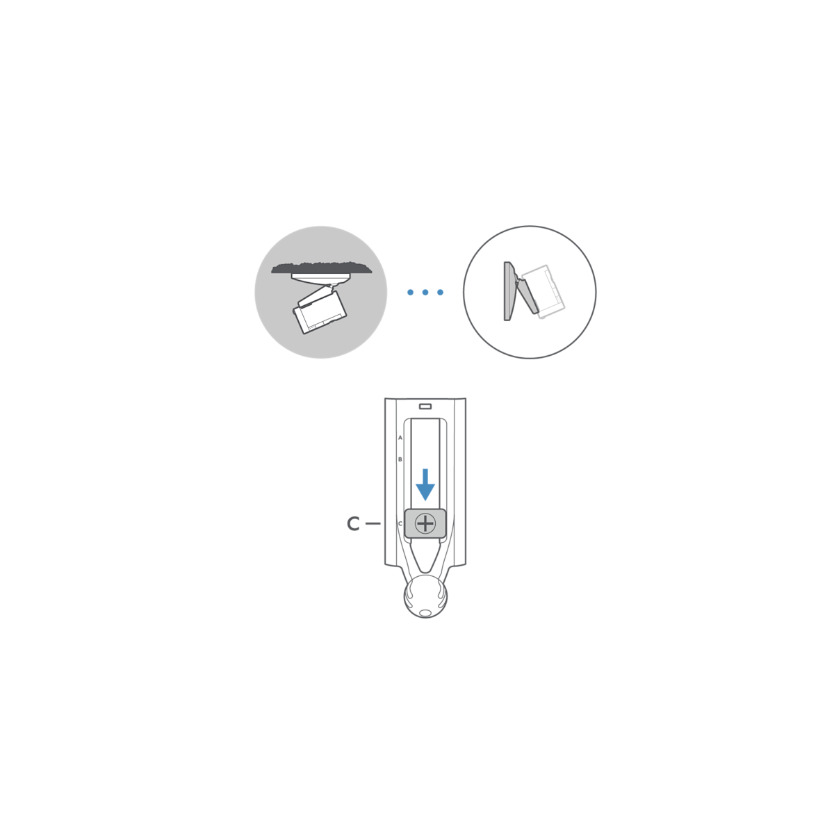
4a. If installing on the wall, slide the hand screw to setting A or B.

4b. If installing on the ceiling, position your camera facing down and slide the hand screw to setting C.
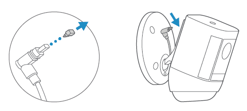
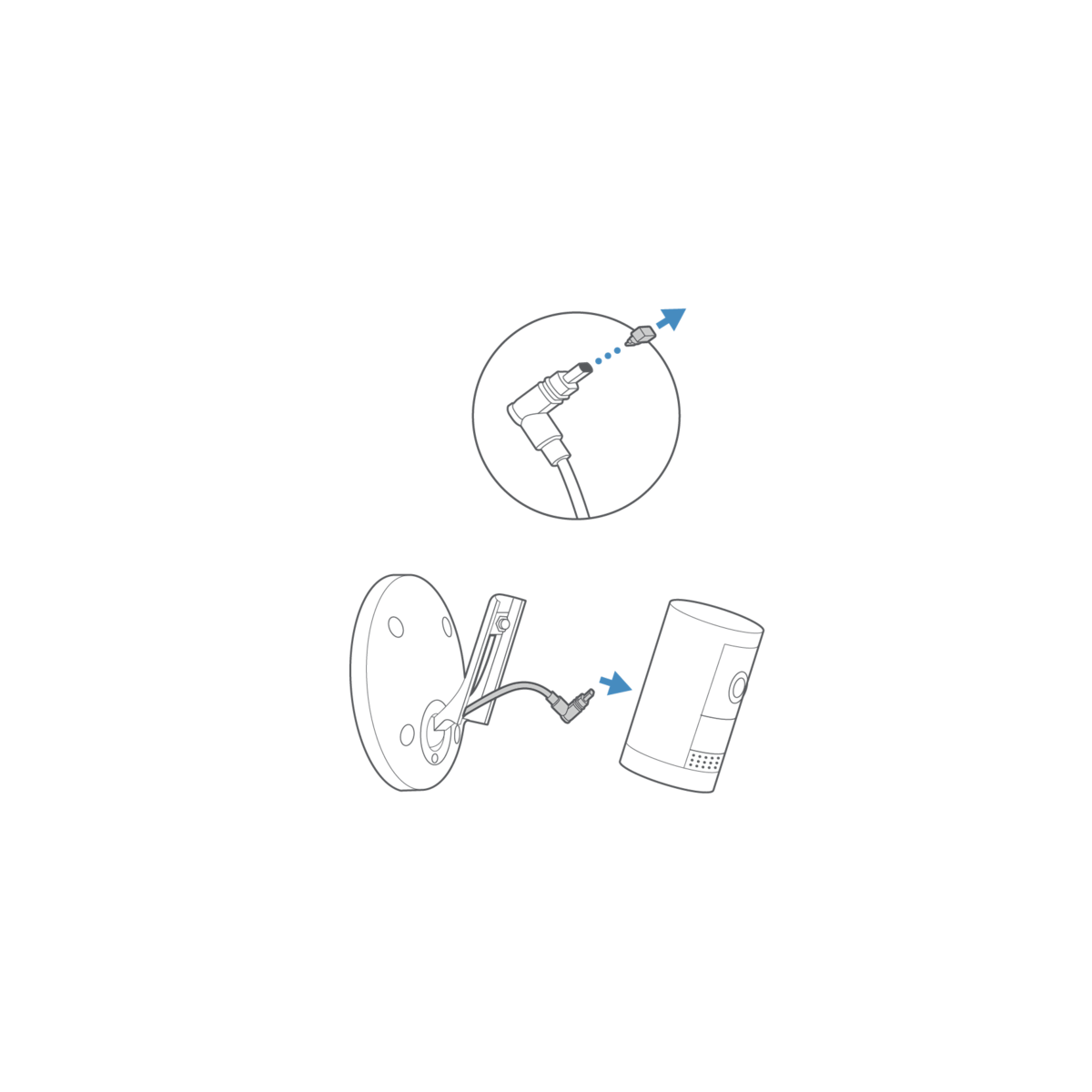
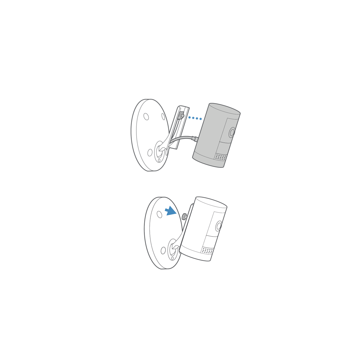
5. Connect the USB-C cable.
Plug the USB-C cable in to your camera’s USB-C port and ensure it is fully connected.
6. Tighten the hand screw until your camera is securely attached to swivel arm.
7. Attach the weather cover.
Snap into place to cover exposed cables.
8. Adjust the camera angle.
Tighten the ball joint screw to secure the camera position, if necessary.
