Installing Outdoor Cam Plus Plug-In
Safety and compliance information for Outdoor Cam Plus.
Learn how to install Outdoor Cam Plus for plug-in use by following these steps.
Note: Outdoor Cam Plus has a larger mounting plate than previous Outdoor Cams or Stick Up Cams. Mounting plates from other cameras cannot be used when installing Outdoor Cam Plus.
View the manual for Outdoor Cam Plus Plug-In (English, Français, Deutsch, Italiano, Español, Nederlands, Svenska, Dansk, Suomi, Norsk, عربي)Hardware included
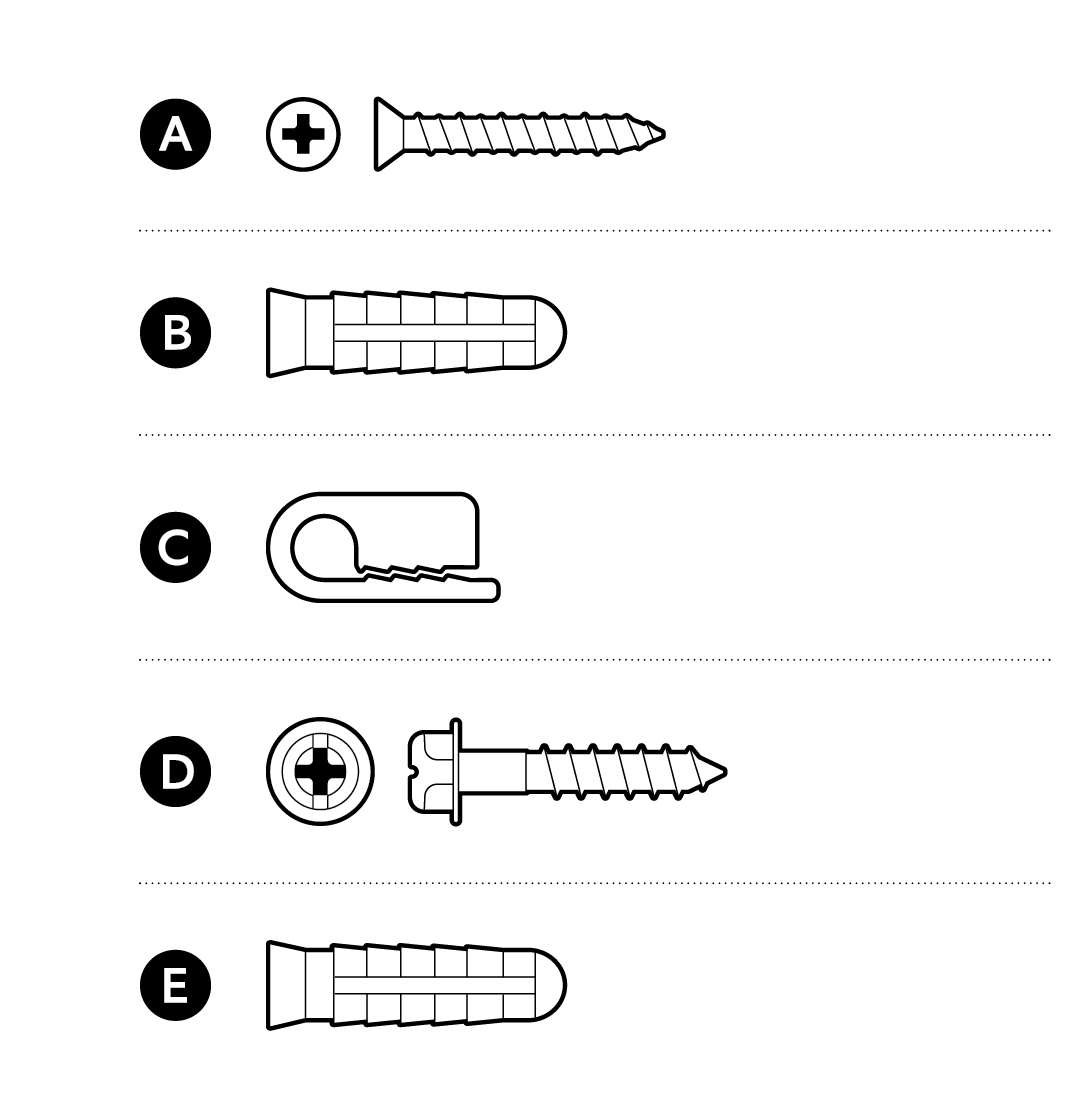
Tools needed
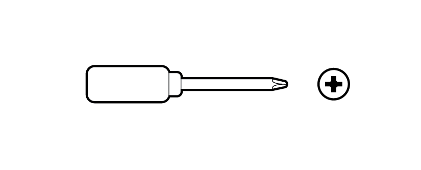
Phillips-head screwdriver
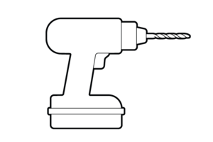
Drill with 1/4 in (6 mm) masonry bit (optional)
1. Remove the rubber cap from your camera's power port.
Note: If you plan on replacing the power adapter with a battery pack, store the rubber cap in a safe place.
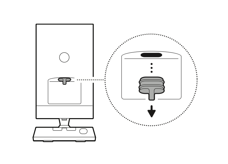
2. Remove the protective wrap.
3. Download the Ring app.

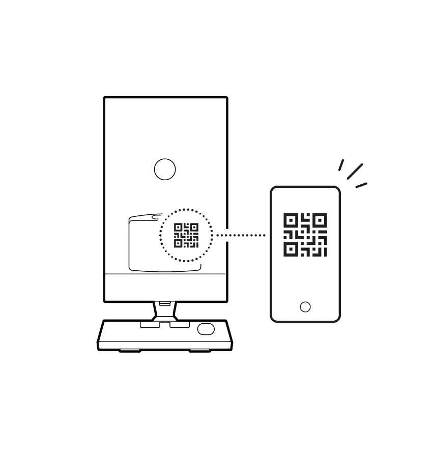
4. Scan the QR code on your device.
5. Choose a mounting location.
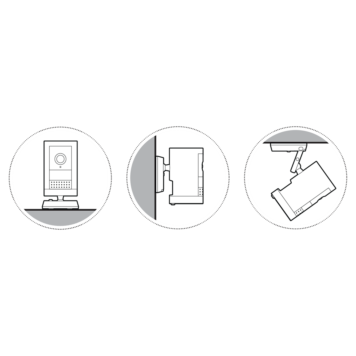
Flat installation
1. Place your camera on a level surface.
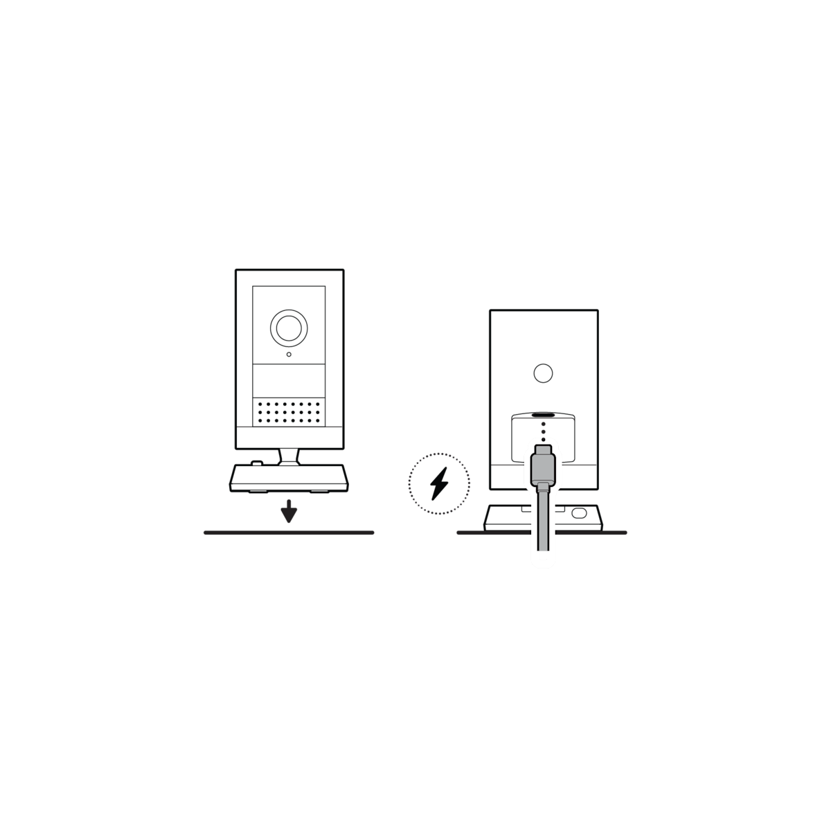
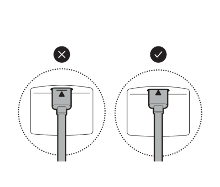
NOTE: For a downward angle, face the longer side of the base toward the front and tilt your camera down accordingly.
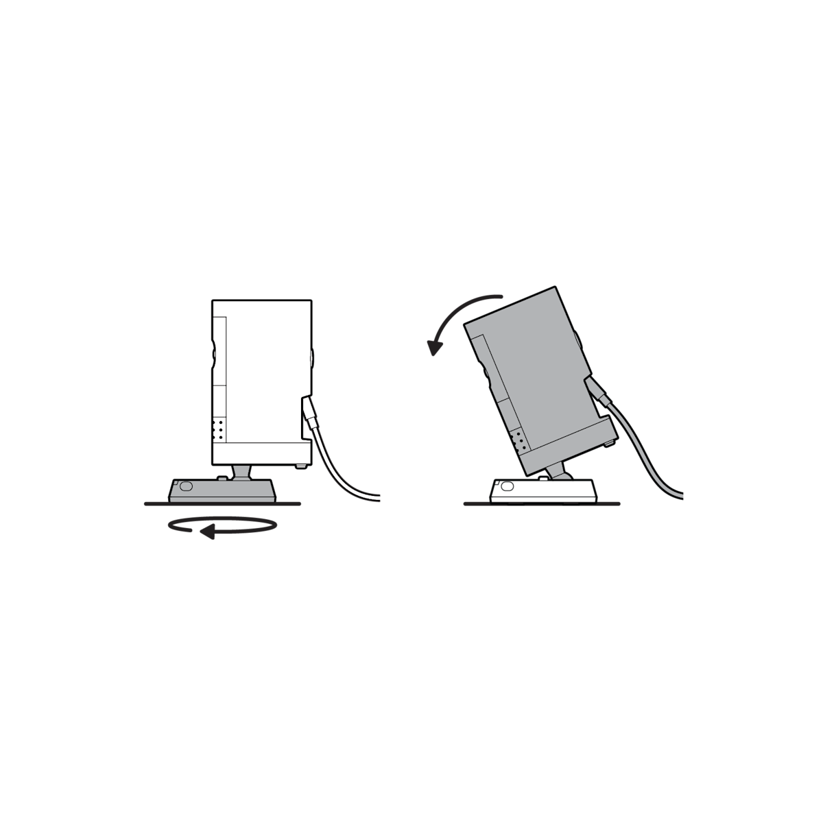
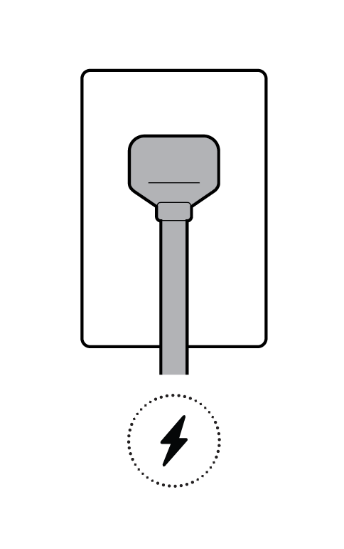
2. Plug the power adapter into an outlet.
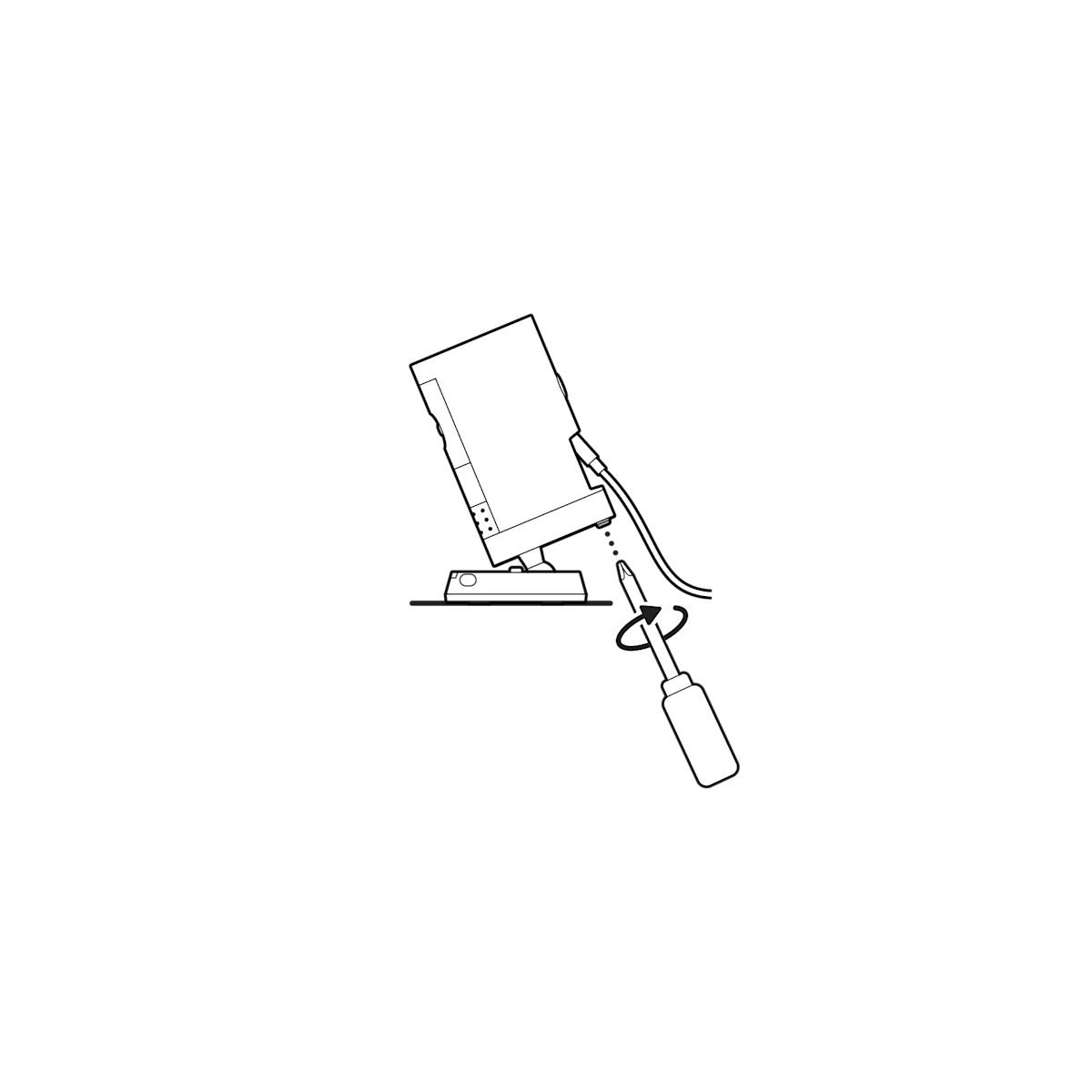
3. Tighten the security screw on the battery cover.
Wall installation
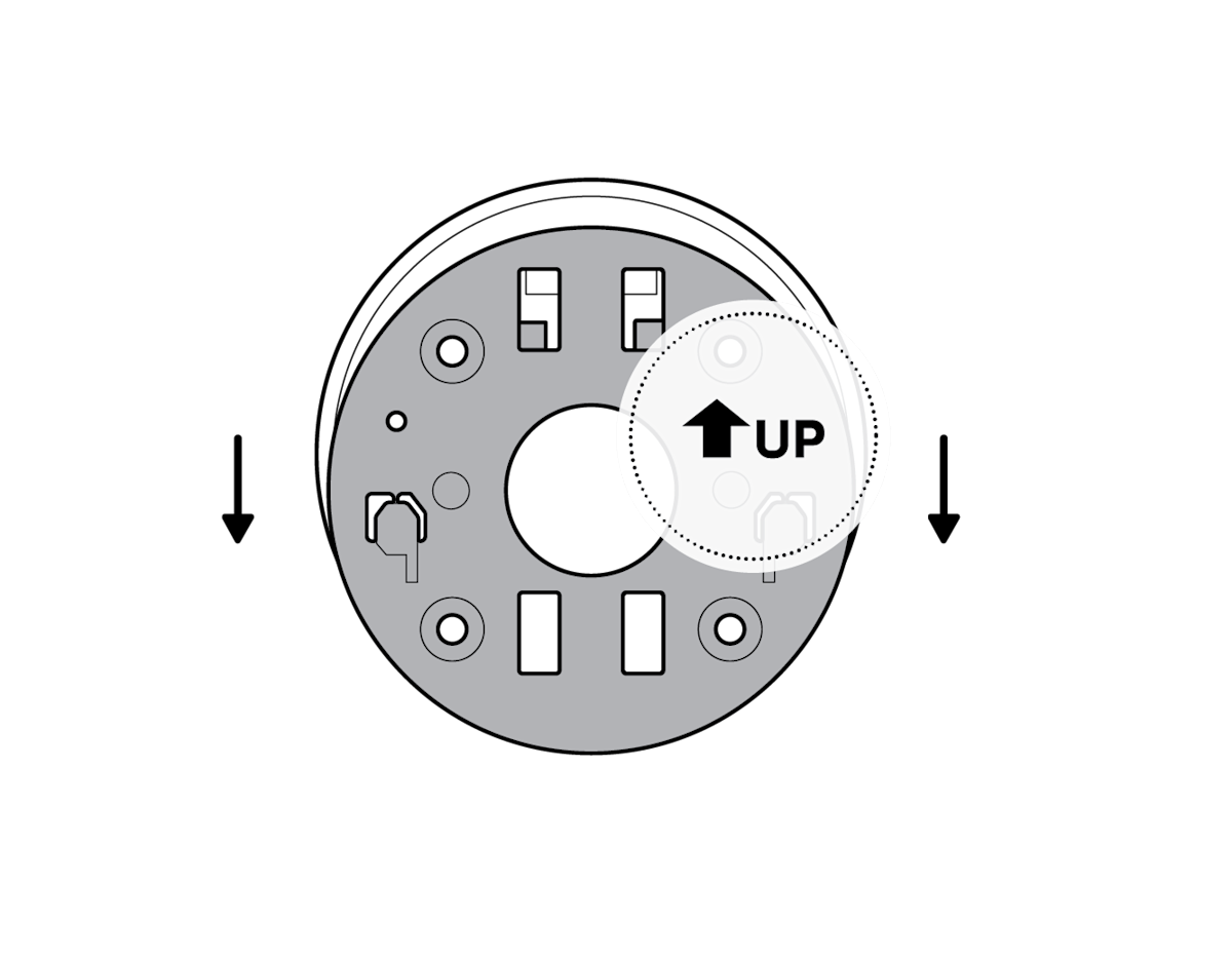
1. Slide the mounting plate in the direction opposite to the UP arrow to remove.
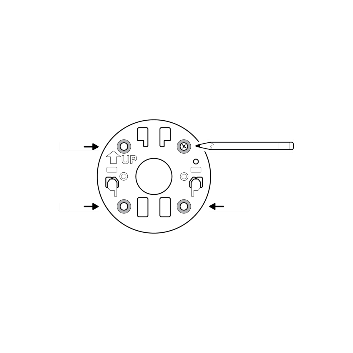
2. Use the mounting plate as a guide to mark screw holes on the wall.
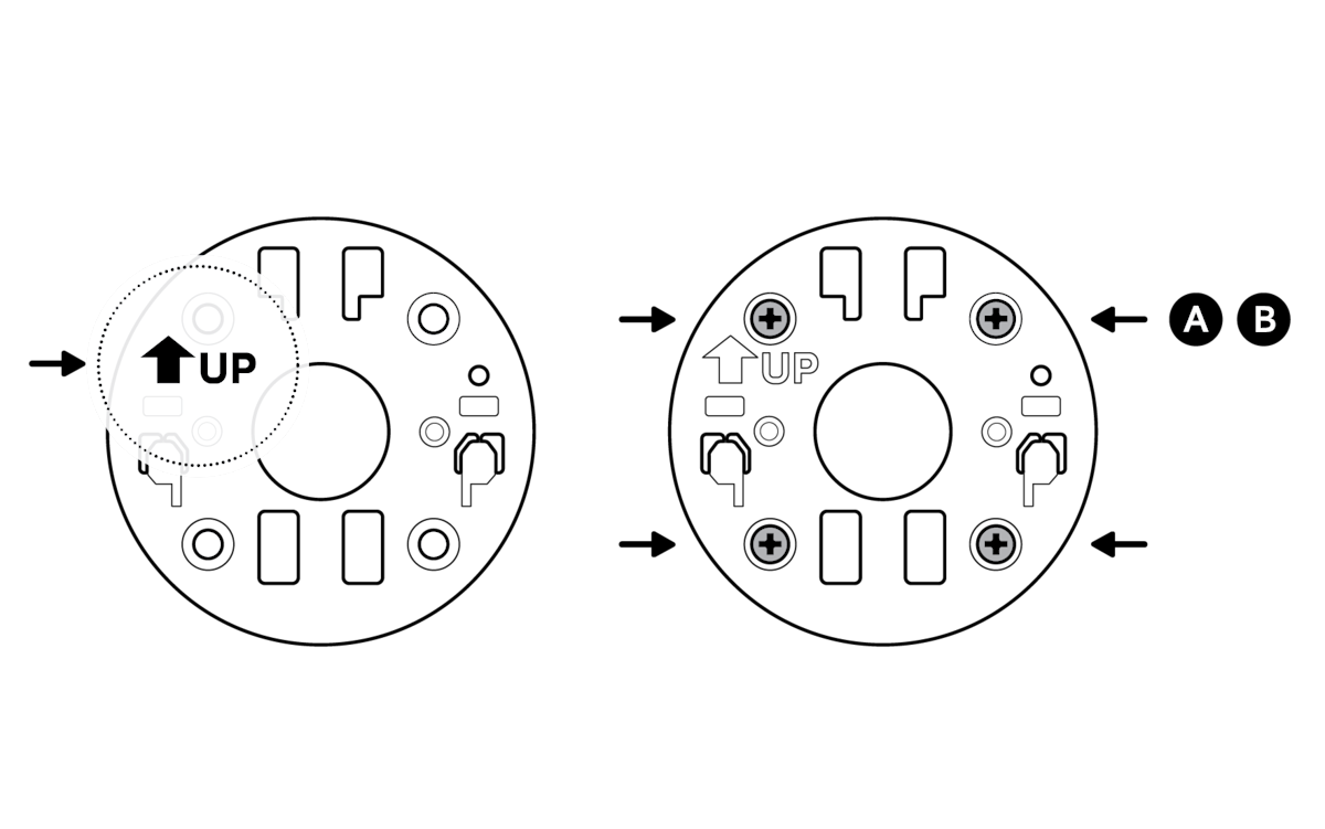
3. Install the mounting plate with the UP arrow pointing up.
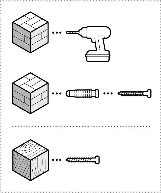
On stucco, brick, or concrete, use a 1/4 in (6 mm) masonry bit to drill holes for the included wall anchors.
4. Unclasp the camera mount.
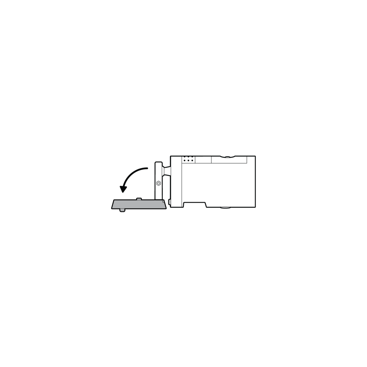
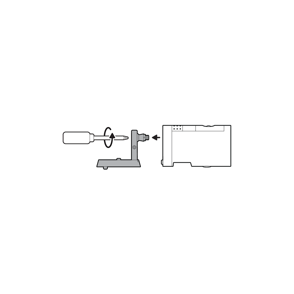
5. Unscrew to detach the camera mount from the battery cover.
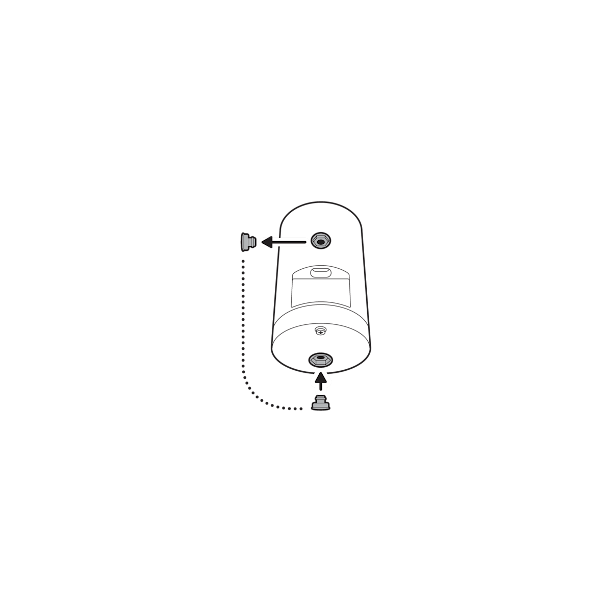
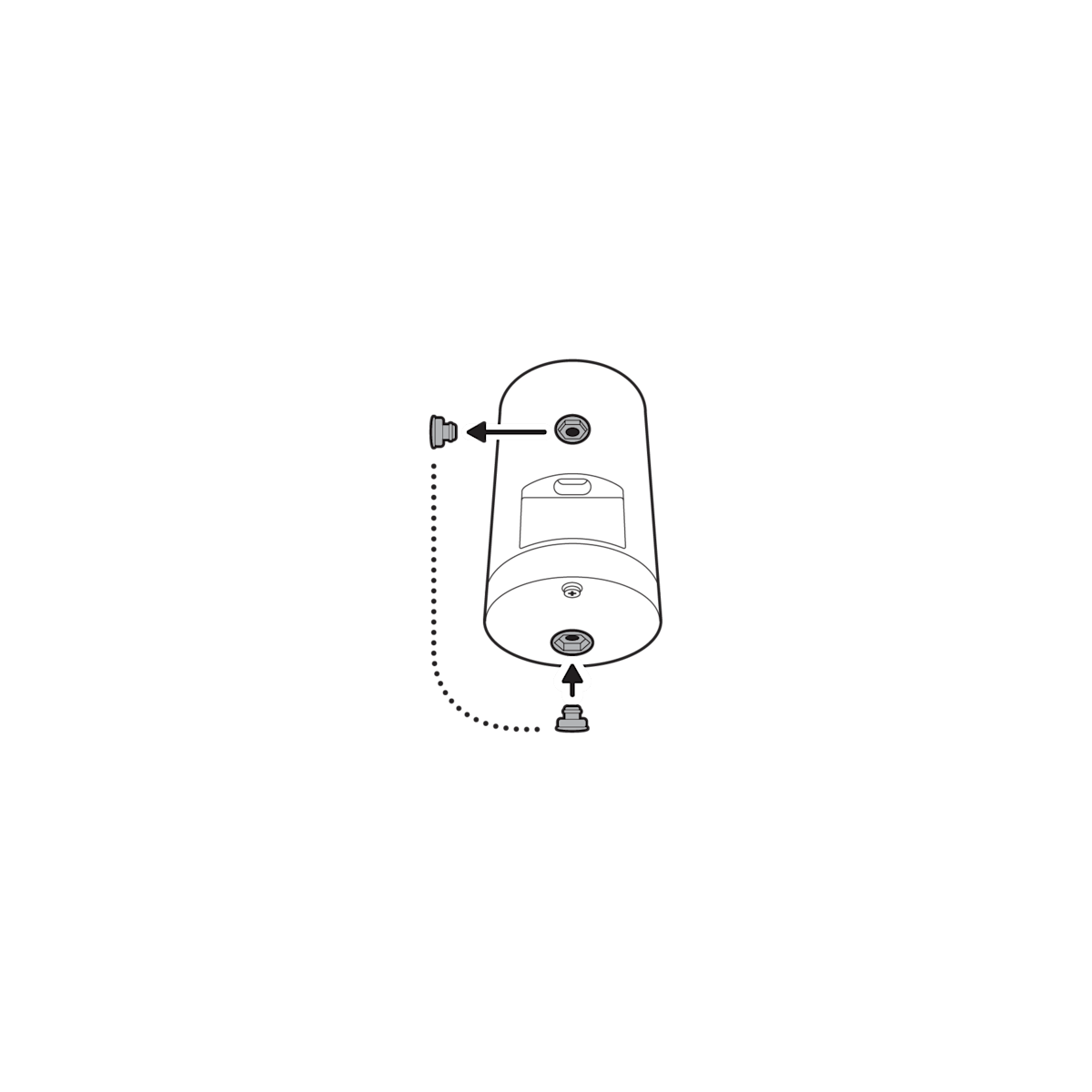
6. Remove the rubber cap on the back of your camera and use it to plug the bottom.
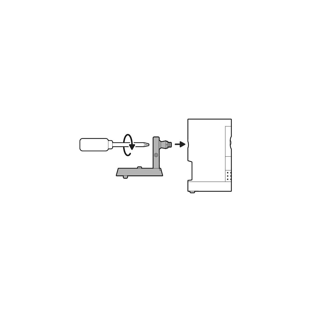
7. Attach the camera mount to the back of your camera with its screw.
8. Plug in the power cable.
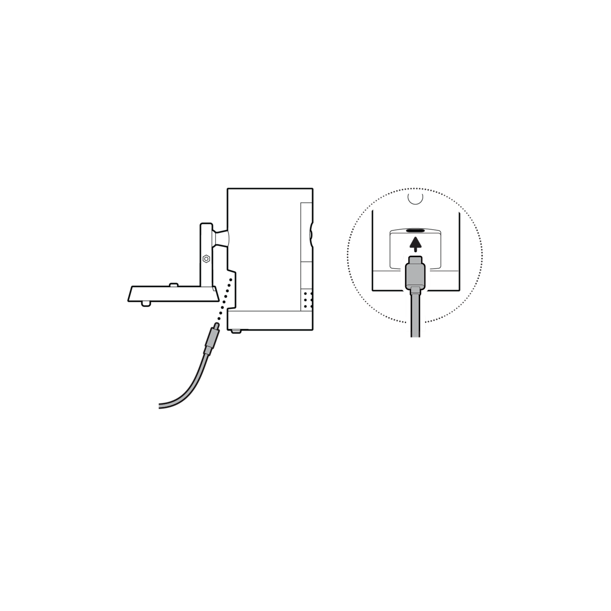

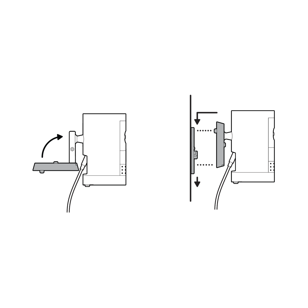
9. Clasp the camera mount and attach your camera to the mounting plate by sliding until you feel a click.
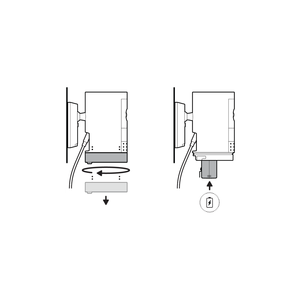
(Optional) If installing with a Quick Release Battery Pack, twist the battery cover to remove. Insert the battery and close.
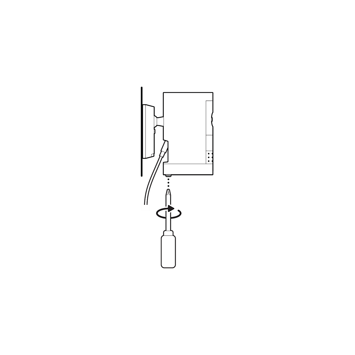
10. Tighten the security screw on the battery cover.
11. Unclasp the camera mount and tighten the security screw.
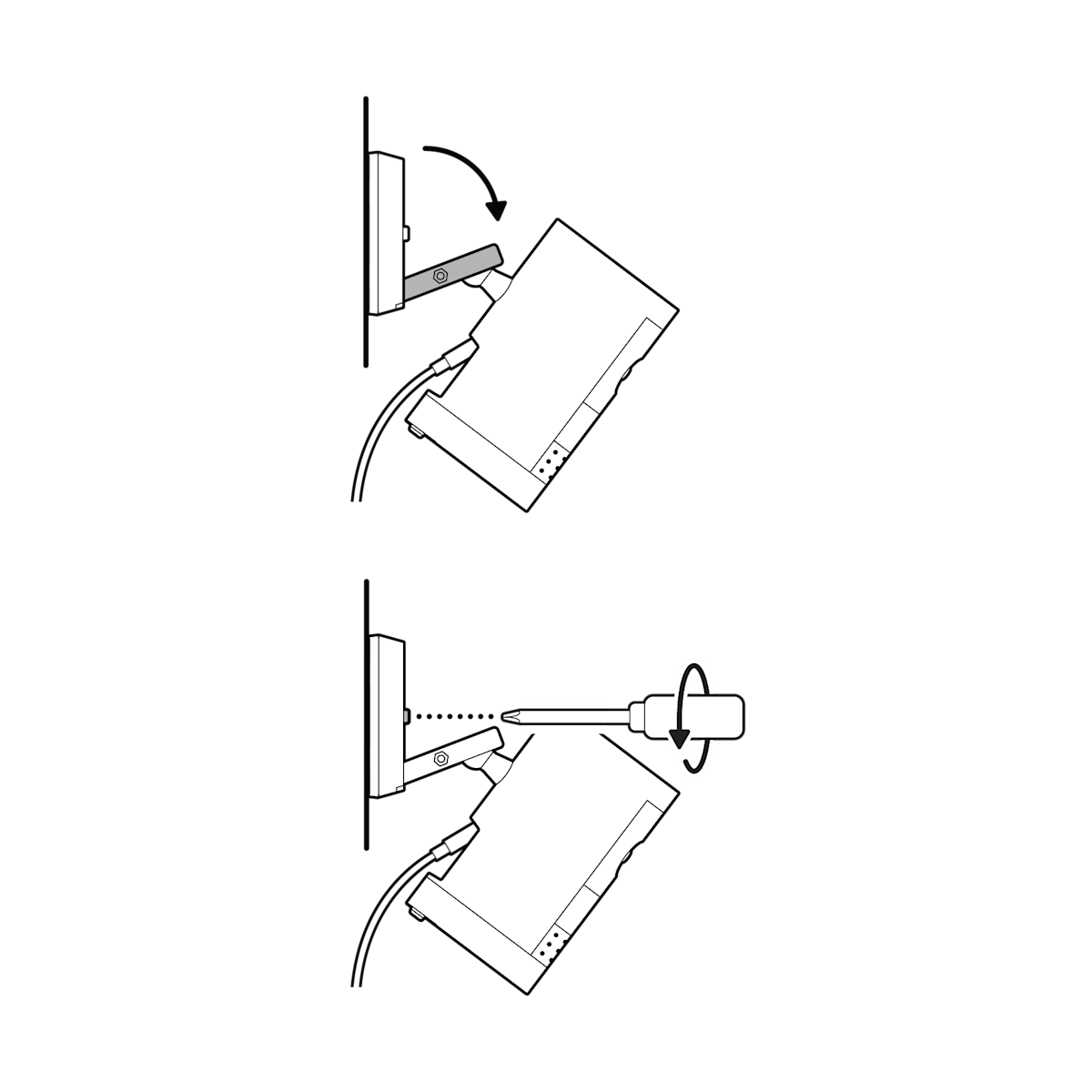
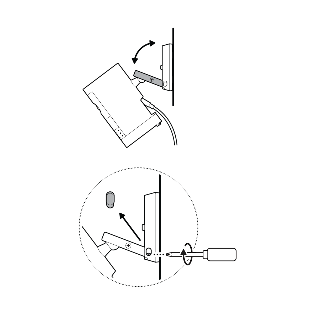
(Optional) Adjust your camera’s position, then remove the rubber cap at the base of the camera mount and tighten the screw to secure in place. Replace the rubber cap.
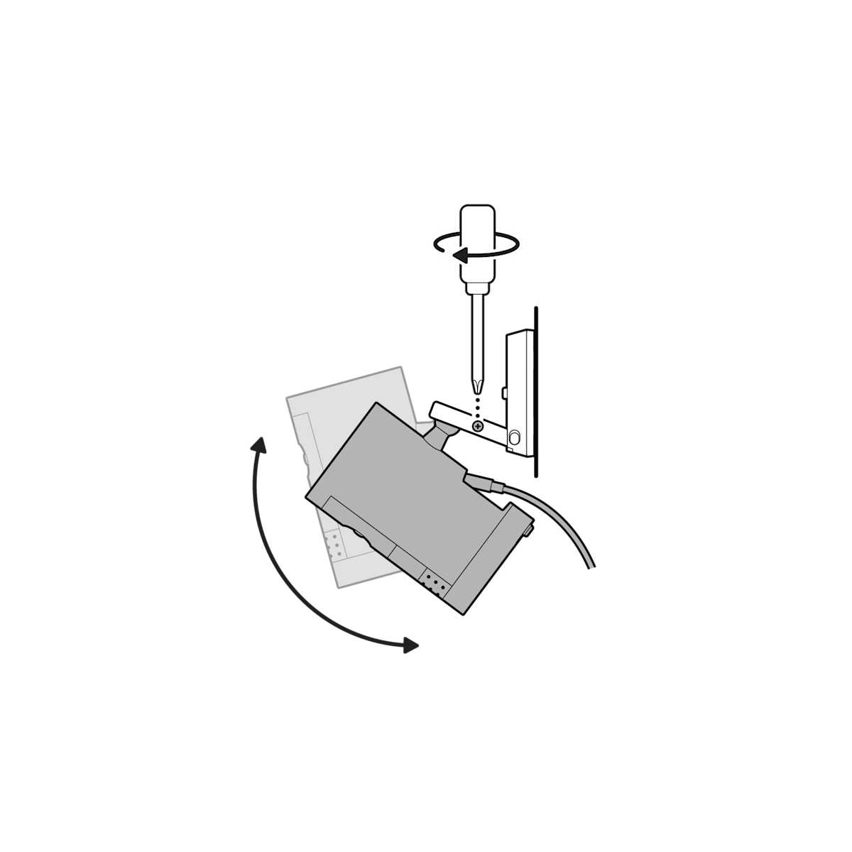
12. Adjust your camera’s angle, then tighten the screw on the camera mount arm to secure in place.
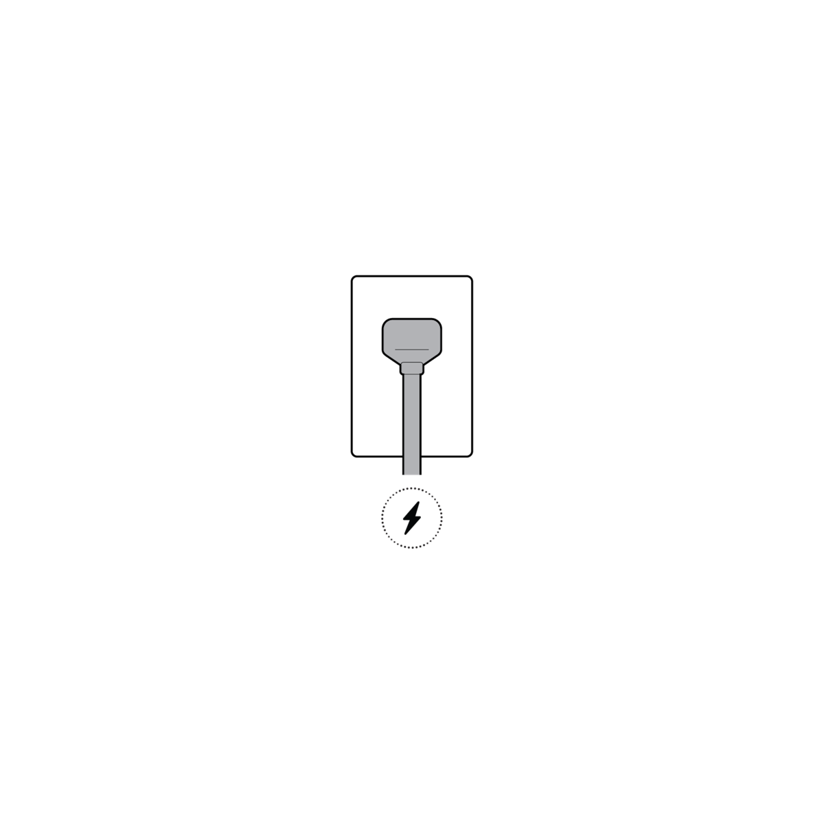
13. Plug the power adapter into an outlet.
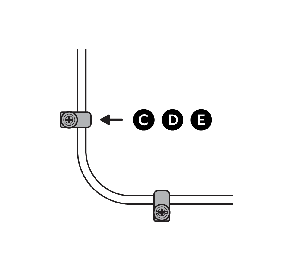
14. Anchor the power cable to the wall or ceiling with the included cable clips.
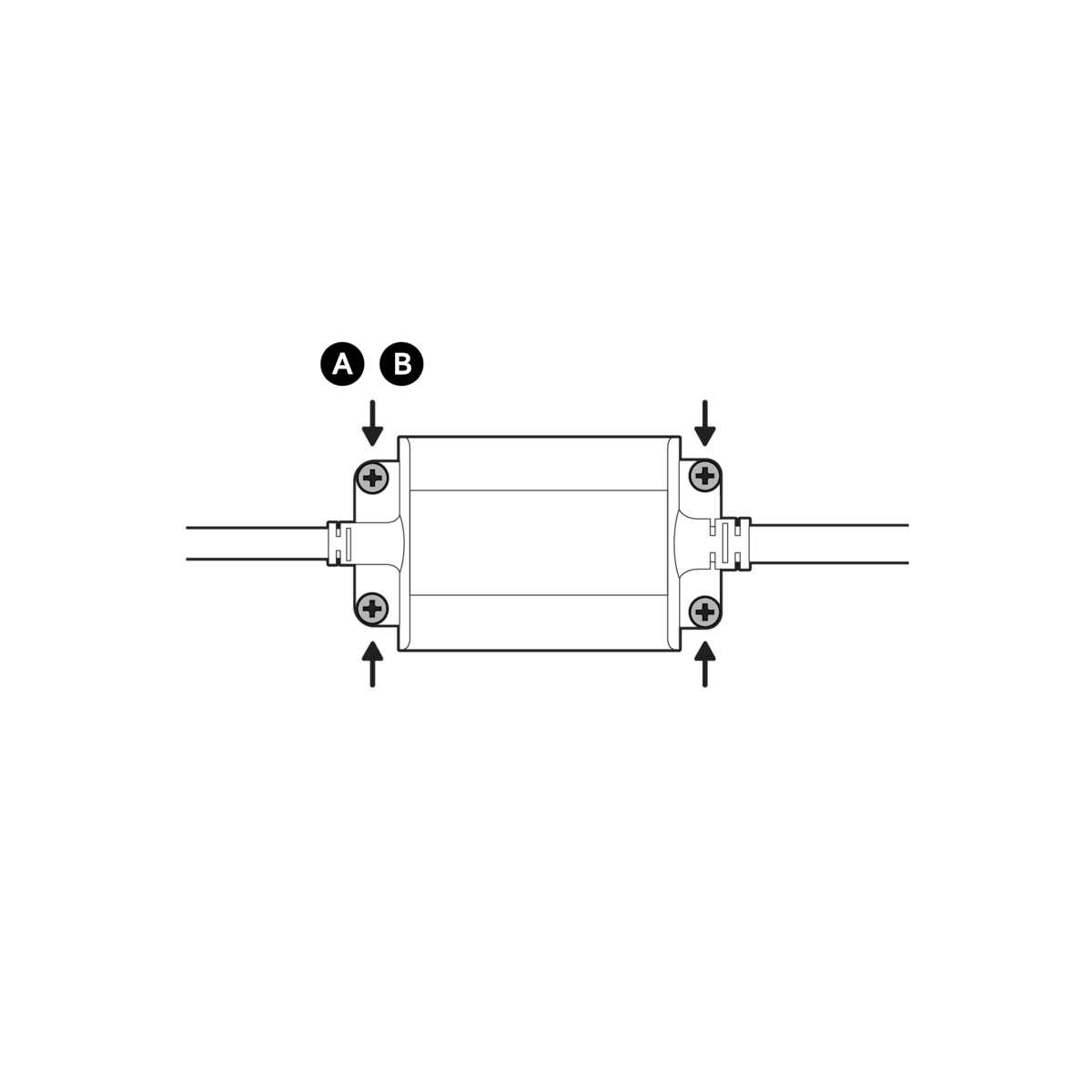
(Optional) Secure the power adapter with the included anchors and screws.
Ceiling installation
1. Slide the mounting plate in the direction opposite to the UP arrow to remove.

2. Use the mounting plate as a guide to mark screw holes on the ceiling.

NOTE: For best results, avoid locations with nearby objects that can interfere with your camera’s field of view.
3. Install the mounting plate with the UP arrow pointing opposite to your desired viewing direction.

On stucco, brick, or concrete, use a 1/4 in (6 mm) masonry bit to drill holes for the included wall anchors.

4. Unclasp the camera mount.

5. Unscrew to detach the camera mount from the battery cover.
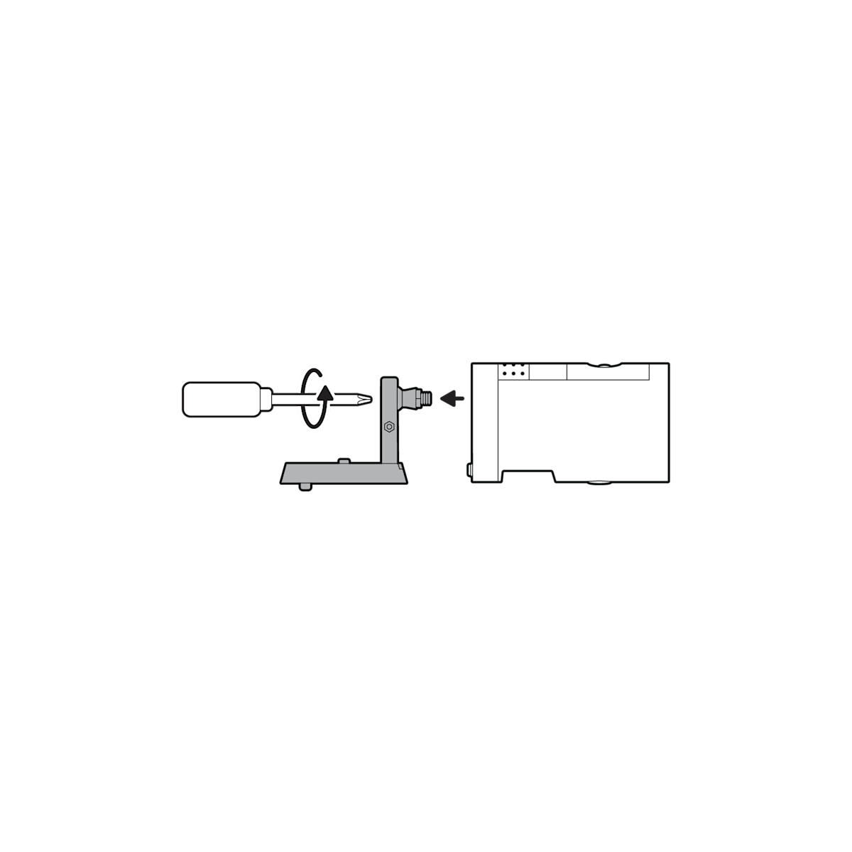
6. Remove the rubber cap on the back of your camera and use it to plug the bottom.
7. Attach the camera mount to the back of your camera with its screw.

8. Plug in the power cable.


(Optional) If installing with a Quick Release Battery Pack, twist the battery cover to remove. Insert the battery and close.
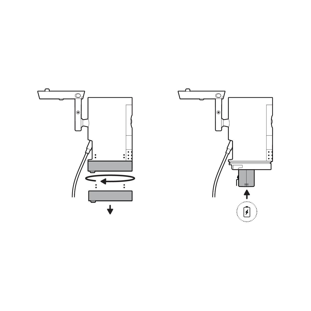
9. Secure your camera to the mounting plate by sliding until you feel a click.

NOTE: Your camera should be in an upright position.
10. Tighten the security screw on the camera mount.
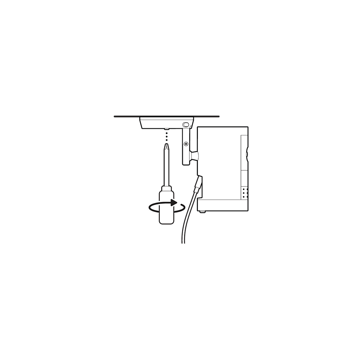
11. Tighten the security screw on the battery cover.
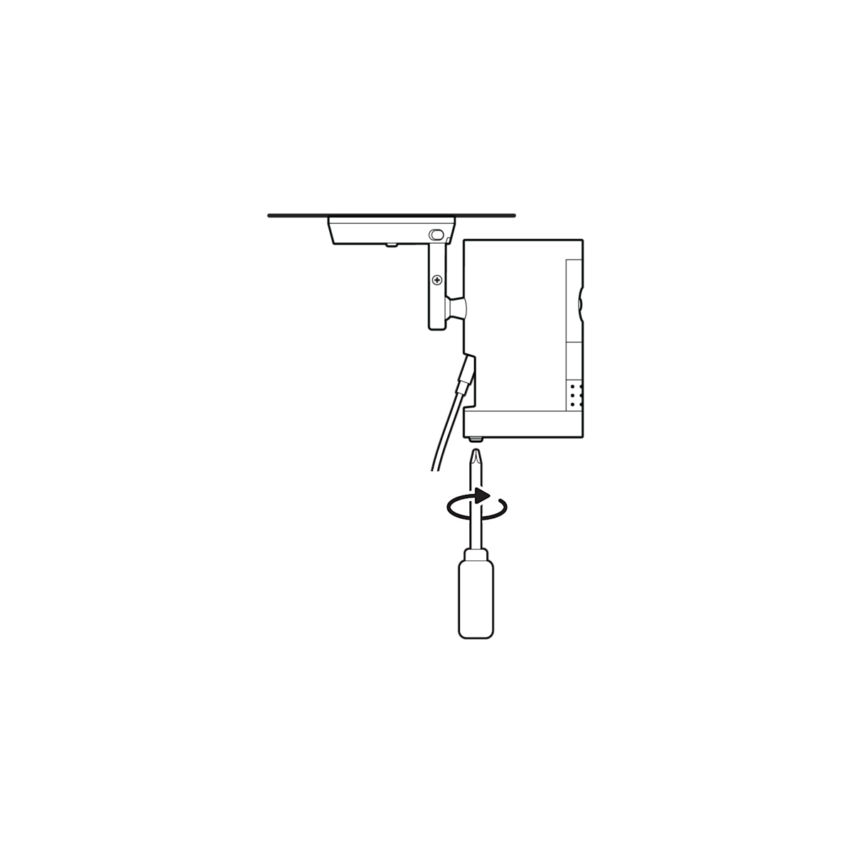
(Optional) Adjust your camera’s position, then remove the rubber cap at the base of the camera mount and tighten the screw to secure in place. Replace the rubber cap.
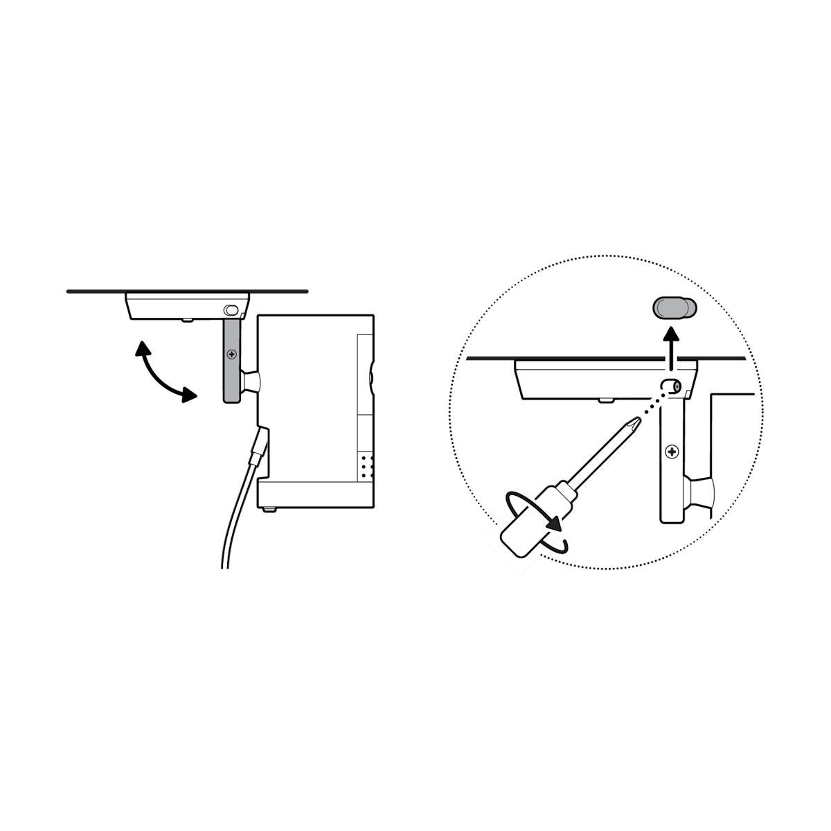
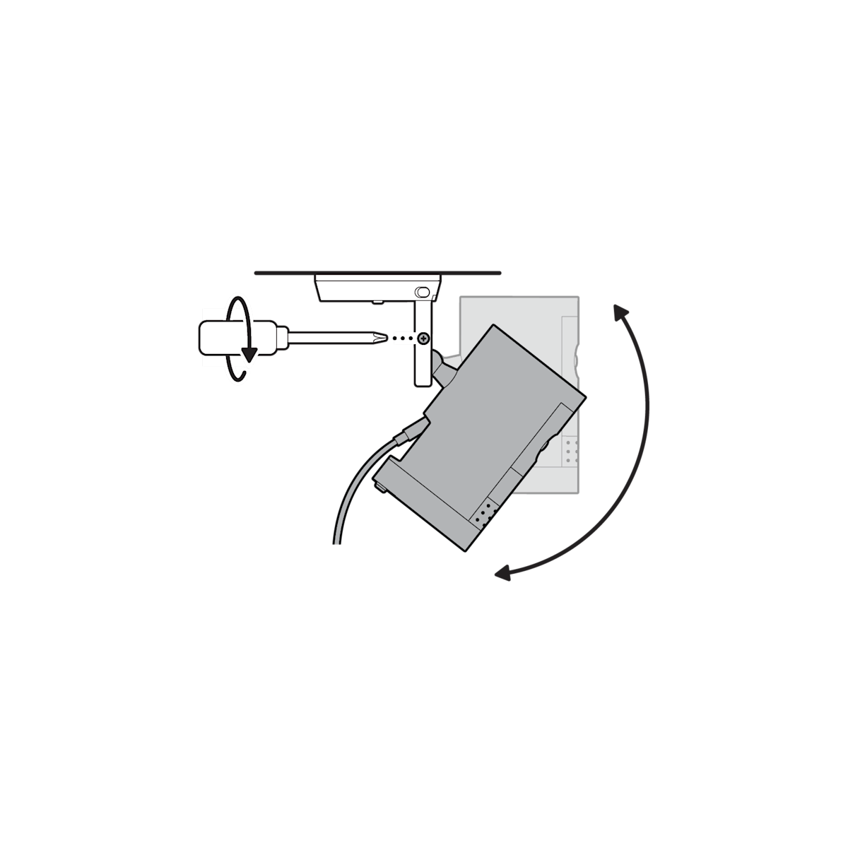
12. Adjust your camera’s angle, then tighten the screw on the camera mount arm to secure in place.
13. Plug the power adapter into an outlet.

14. Anchor the power cable to the wall or ceiling with the included cable clips.

(Optional) Secure the power adapter with the included anchors and screws.

